


Blog - TECHNICAL TIPS & TRICKS - Solid State Relays - The most frequent thermal design errors with Solid State Relays
Solid state relays are now widely used in industrial machines for their reliability, fast switching, and absence of mechanical wear. However, this image of robustness can be misleading. In practice, a significant proportion of SSR failures observed in the field originate from insufficiently controlled thermal design.
Unlike electromechanical relays, an SSR continuously dissipates power as soon as it conducts current. If this dissipation is not properly removed, it leads to an increase in the junction temperature of the power components, with direct consequences on performance, reliability, and system lifetime. Thermal design must therefore never be considered a simple validation detail, but a full architectural choice in its own right.
The purpose of this mini-guide is to identify the most common errors encountered in the thermal design of SSRs and to propose concrete best practices for engineering design offices.
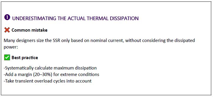
One of the most common mistakes is sizing a solid state relay solely based on the nominal load current, without accurately evaluating the power dissipated by the component. Yet the thermal dissipation of an SSR is directly linked to the internal voltage drop when it is conducting. Even a seemingly low value becomes critical when the current is high and continuous.
A solid state relay conducting 40 A with a voltage drop of around 1.6 V will therefore dissipate more than 60 W of heat in continuous operation. This power must absolutely be evacuated to the outside. Neglecting this calculation leads to designs that appear correct on paper but quickly prove limited under real conditions, especially at high ambient temperatures or in closed cabinets.
A good practice is to always calculate the maximum dissipation, taking into account worst-case operating conditions and adding a safety margin for transient overloads or component tolerances.
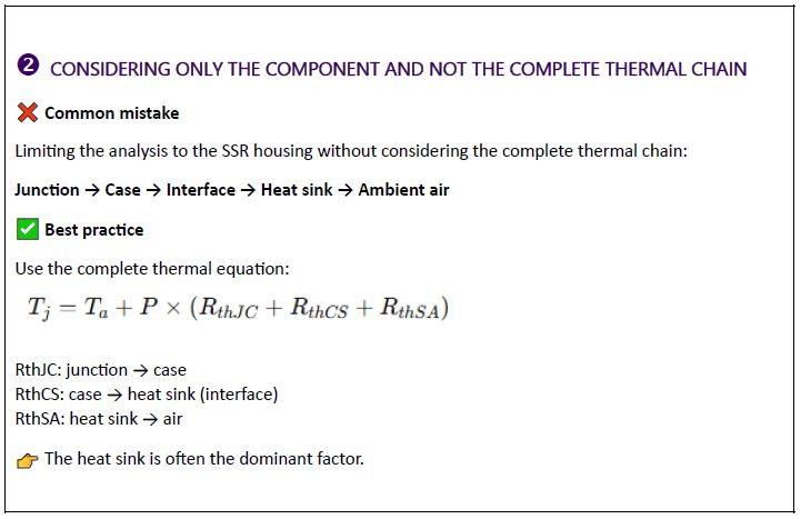
Another classic mistake is treating the SSR thermal resistance as an isolated parameter. In reality, the junction temperature depends on the entire thermal chain, from the internal semiconductor junction to the ambient air.
Heat must successively pass through the relay housing, the mounting interface, the heat sink, and finally be transferred to the surrounding air. Each of these stages introduces thermal resistance that adds to the others. Focusing only on relay characteristics without integrating the heat sink, thermal interface, and environment leads to very optimistic estimates of operating temperature.
A rigorous approach consists of calculating the junction temperature from the actual ambient temperature inside the cabinet, integrating all thermal resistances of the system. In many cases, the heat sink and its interaction with ambient air represent the dominant part of the problem.
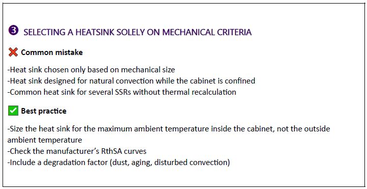
The heat sink is often selected late in the project, sometimes only based on space constraints or mechanical standardization. This approach frequently results in undersized heat sinks, incapable of dissipating the power generated by the solid state relay under realistic conditions.
It is also common to assume ideal natural convection, while the heat sink is installed in a confined cabinet with limited airflow disturbed by wiring or other heat-generating equipment. When several SSRs share the same heat sink, the cumulative effect is often underestimated, increasing hot spots.
A heat sink must always be sized for the maximum temperature actually reached inside the electrical cabinet, not for the outside ambient temperature. The thermal performance curves provided by celduc® on its website must be used with caution, integrating degradation factors related to installation conditions.
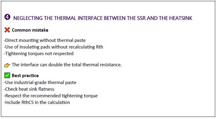
The thermal interface is sometimes perceived as a simple assembly detail, although it plays a key role in heat dissipation. Mounting without thermal paste, inappropriate use of insulating pads, or failure to respect tightening torque can significantly degrade heat transfer between the relay and the heat sink.
A poor interface alone can double the total thermal resistance of the system, thus canceling the benefits of a properly sized heat sink. The flatness of the contact surfaces and the quality of the interface material are decisive in ensuring efficient and repeatable thermal conduction.
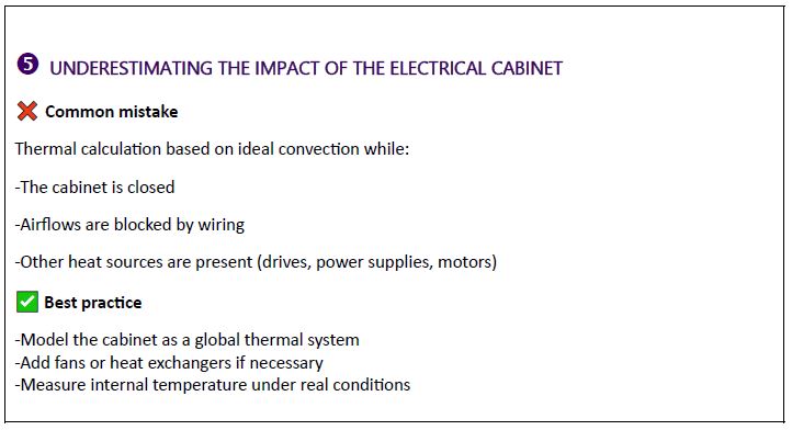
Many thermal studies are carried out assuming a constant and homogeneous ambient temperature, without considering the reality of the electrical cabinet. In practice, the inside of a cabinet can reach temperatures well above the external ambient temperature, especially when several heat-generating devices are grouped together.
Variable speed drives, power supplies, transformers, and solid state relays all contribute to overall heating. Without proper ventilation or airflow management, the internal temperature can quickly become the limiting factor of the system. Reliable thermal design therefore requires a global vision of the cabinet, not a component-by-component analysis.
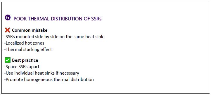
Poor thermal distribution of SSRs (Solid State Relays) is a common mistake in electrical cabinet design. It notably occurs when several solid state relays are mounted side by side on the same heat sink, creating localized hot zones and causing a thermal stacking effect. This heat accumulation can lead to excessive temperature rise, reduce component lifetime, and increase the risk of failure. To avoid these issues, it is recommended to space SSRs to limit thermal interactions, use individual heat sinks when dissipated power is high, and favor a homogeneous thermal distribution that enables better heat evacuation and more reliable system operation.
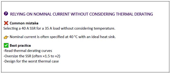
The nominal current of a solid state relay is generally specified under ideal conditions, often at 40 °C and with an optimized heat sink. Using this value as the main selection criterion, without analyzing thermal derating curves, leads to marginal choices.
As temperature increases, the allowable current capacity of the SSR decreases. In many industrial cases, it is necessary to oversize the relay, sometimes by a factor of 1.5 or even 2, to ensure reliable operation over the entire expected temperature range.
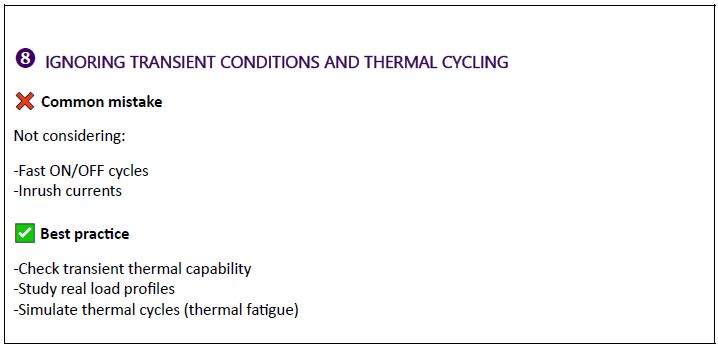
Thermal design must not be limited to steady-state operation. ON/OFF cycles, inrush currents, highly inductive loads, or fast modulation control generate significant transient thermal stresses.
These repeated temperature variations create internal mechanical stresses in semiconductors and interfaces, accelerating thermal fatigue phenomena. A realistic analysis must integrate the actual load profile of the application, not an idealized steady-state operation.
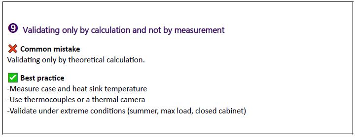
Finally, a common mistake is considering the thermal study validated once calculations are completed. In practice, only measurement under real conditions can confirm the relevance of a design. Assembly tolerances, environmental variations, and simplifying assumptions make a field validation phase essential.
Measuring case, heat sink, and ambient air temperatures using thermocouples or thermal cameras makes it possible to identify real margins and anticipate problems before commissioning.
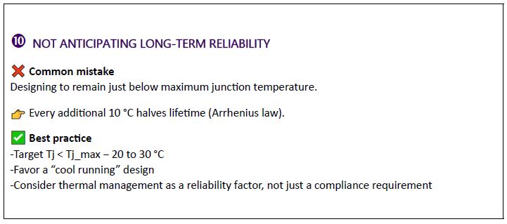
Failing to anticipate long-term reliability is a classic mistake in electronic design. Designing a system to operate just below the maximum junction temperature (Tj_max) may seem compliant with specifications, but it significantly weakens component lifetime. According to the Arrhenius law, every 10 °C increase can divide component lifetime by two, making small thermal margins particularly risky. Good practice therefore consists of targeting a junction temperature 20 to 30 °C below the maximum allowable value, adopting a so-called “cool running” design. Thermal management must be considered not only as a technical compliance requirement, but as a major driver of long-term system reliability and durability.
Thermal management of solid state relays must not be approached as a secondary constraint, but as a major lever for reliability and performance. A design that keeps junction temperature significantly below the maximum limit considerably improves system lifetime and reduces the risk of premature failure.
By integrating thermal considerations from the earliest design phases, adopting a global approach, and validating through measurement, engineering design offices can transform a frequently endured constraint into a true design advantage.
![]()
D‑U‑N‑S® Number : 117690071
Phone : 312-420-0519
434 E. Main Street, #429
Centerport NY 11721
USA

