


Blog - TECHNICAL TIPS & TRICKS - Solid State Relays - Thermal management


In modern electronic applications, temperature control is a key factor in ensuring the reliability, safety, and longevity of components. This is especially true for solid-state relays (SSRs), whose performance can quickly degrade if the heat they generate is not properly dissipated. Excessive heating can shorten the component’s lifespan, impair its operation, or, in severe cases, lead to failure.
Thermal management is not just about picking any heatsink—it requires a solid understanding of the basic heat transfer mechanisms (conduction, convection, and radiation) and strict adherence to the manufacturer’s recommendations. This blog post provides an overview of essential thermal principles, best installation practices, and how to interpret the thermal curves provided by Celduc. Whether you’re a designer or system integrator, this guide will help you ensure effective cooling of your SSRs and maintain their optimal performance over time.
It is not uncommon for the life expectancy of electronic equipment to be at least 10 years, with many applications looking for 25 years or more. As such, thermal considerations must be fully addressed at the design stage of the electronic circuitry. Heat transfer is energy in transit due to a temperature difference.
It is well known that the useful life and reliability of semiconductors improves with lower operating temperatures. The temperature of a semiconductor junction, Tj, is the main criterion for its reliability and performance. Its maximum allowable value, Tj (max), is specified by the semiconductor manufacturer.
During energy conversion in a semiconductor, part of the electrical energy transforms to heat. This generation of heat, otherwise known as heat losses, is proportional to 1-e, where e is the semiconductor efficiency as specified by the manufacturer. If not removed, this heat will cause the junction temperature to rise above that allowable, resulting in damage and eventual failure of the semiconductor.
The typical 1.2-volt on-state drop (at maximum current) across the output terminals is responsible for most of the dissipation in both AC and DC SSRs, regardless of operating voltage. At lower currents the voltage falls slightly and creates a nonlinearity in the power dissipation versus current curves, as shown in data sheets.
The three fundamental modes of heat transfer are conduction, convection and radiation.
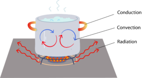
Heat transfer that occurs across a stationary medium is termed conduction. It is usually thought of as the heat transfer through solid materials, although it also occurs in fluids. Fourier’s law describes heat flow, Q (heat energy transferred per second -Watts), through a solid layer.
Convection is the mode of heat transfer that occurs at the interface between a solid surface and surrounding fluid. The fluid layers adjacent to the solid surface become warmer and flow away to cooler portions of the fluid. There are two distinct types of convection classified according to the mechanism of the fluid flow: namely, natural convection and forced convection.
Natural convection occurs when the fluid flow is a result of the natural buoyancy forces within the fluid.
Forced convection occurs when the fluid flow is caused by external means, such as a fan, pump or atmospheric winds.
Convection heat transfer is described by Newton’s law of cooling.
Radiation heat transfer is energy emitted by matter that is at a finite temperature, transported by electromagnetic waves. While the transfer of energy by conduction or convection requires the presence of a material medium, radiation does not. In that any object or body at some finite temperature emits radiation, that implies that every object or body is also the recipient of radiation from the bodies surrounding it, net radiation heat exchange between a surface and its surroundings.
One of the most important aspects to consider in the use of solid-state relays is the thermal design. It is essential that the user provide an effective means of removing heat from the SSR package. This is because of the relatively high dissipation, in excess of 1 watt per ampere, compared to milliwatts for the EMR. The importance of using an adequate heat sink cannot be omitted, as it directly affects the maximum utilizable load current and/or maximum allowable ambient temperature. Lack of attention to this detail can result in improper switching or even total destruction of the SSR. With SSR loads of less than 5 amperes, cooling by free flowing convection or forced air currents around the basic package is usually sufficient. At higher currents it becomes necessary to effectively expand the exposed radiating surface area by means of a suitable heatsink. This requires that the SSR be firmly mounted to a smooth flat surface on a good heat conductor such as copper or aluminum, plus the use of a thermally conductive compound to improve the interface. Using this technique, the SSR base to heatsink thermal resistance (RƟBS) is reduced to around value of 0.l°K/W (Kelvin per watt). This is usually presumed and included in any given thermal data. The values that are determinable by the user are the base to heatsink interface and the heatsink to ambient interface.
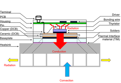
As the power components are inside a housing, they are not able to radiate and therefore most of the thermal energy is consumed by conduction.
Nevertheless, environment inside of the SSR housing is heated by the power element and there is small radiation if air is present.
The resistors correspond to the resistance to transmit the heat. The capacitors, combined with the resistors corresponds to the thermal inertia (reaction time).
For these cases the resin, internal heatsink (baseplate or built-in heatsink) and enclosure act as a dissipator to transmit heat to the surrounding environment. For example in a SK package, the junction to ambient air thermal resistance is in the region of 20 to 25 ºC/W
Max PD = (Max. junction temperature – Ambient temperature) / 20 max
PD = (110 – 30) / 20 = 4 Watts, hence max. rms I at 30ºC ambient temperature is 4 Amp. For each SSR, a curve specifies the maximum current according to the ambient temperature and built-in or external heatsink.
The heatsink can be determined either by calculation or directly from the derating curves provided by Celduc. For more information about the determination by calculation : read our technical note.
Some thermal curves without heatsink are given for celduc solid state relays. When mounted on the backplate or a cabinet wall, the SSR – plate contact must adequate.
An aluminum backplate of reasonable thickness (3-5 mm) with dimensions of 150mm x 150mm corresponds to approximately 4 ºC/W, if it’s in contact with ambient air.
An aluminum backplate of reasonable thickness (3-5 mm) with dimensions of 300mm x 300mm corresponds to approximately 2 ºC/W, if it’s in contact with ambient air.
In all cases, user must perform a test and measure the heat on the SSR baseplate.
There are some applications where various solid state relays are mounted on one heatsink fixed to backplates of cabinets. This solution optimizes space by maximizing heatsink thermal capacity at the time of equipment heating or preheating, when all the solid state relays are operating permanently. The value of the thermal constant of Celduc heatsinks is specified.
To determine the heatsink characteristics, consider the total power to be dissipated for all the SSRs. Perform thermal resistance calculation required: Rth = T/ Pd . The safest approach is to conduct a temperature rise test at the worst operational conditions, to confirm that temperature of the heatsink does not exceed the maximum specified.
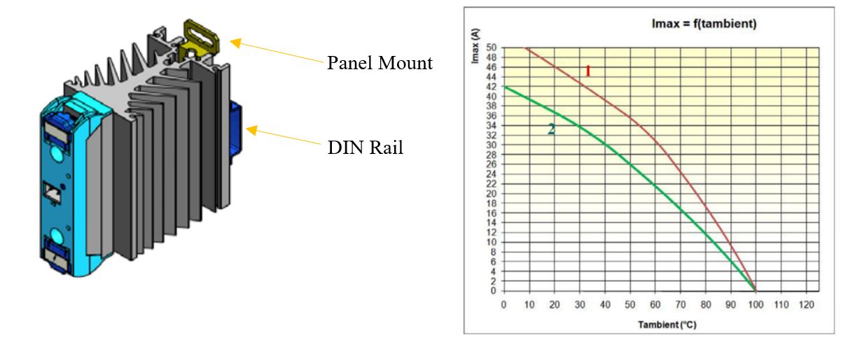
celduc offers a wide range of ready to use relays which can be mounted on a DIN rail or screwed on a panel or cabinet wall. The values of the switching current are directly specified in compliance with the European Standards, corresponding to limited temperature rises of maximum 50 ºC for heatsink and maximum 50 ºC for housing/cover, the corresponding derating curves included on each Celduc ready to use SSR indicate the ratings on which such model can operate in function of surrounding ambient temperature.
![]()
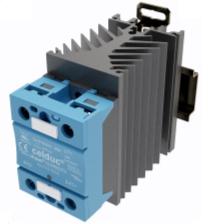
The thermal interface (TIM) improves heat transfer between the SSR and heatsink. As there are cavities between both surfaces and as the air is not good heat conductor, it’s used to fill voids to maximize the heat transfer. The picture, that you can see opposite, shows the action of the thermal grease (in orange), but it also shows as well that the heat transfer is better when metal surface is in contact with other metal surface. There are different types of thermal interfaces (TIM) such as Thermal Compounds and Thermal Pads.
To learn more about the difference between “Thermal Pads” and “Thermal Paste” and How making the right choice ?
Values of power dissipated according to the current crossing the relay are given for permanent operation on the derating curves specified by Celduc. For applications with intermittent operation, some datasheets curves provide the power rating with a duty cycle = ton / toff <1, but such values are only valid for short periods of time, meaning less than the thermal time constants of the heatsinks.
The thermal resistance of a heatsink is defined in determined mounting conditions to optimize its efficiency such as vertical mounting.
In the case of a severe atmosphere applications (cabinet with no air flowing), safe factor (20 to 30%) must be included when heatsink calculation is performed.
Thermal resistance values of Celduc heatsinks are given under natural convection conditions, in the vertical position (fins aligned with air flow) and inside of a cabinet.
Forced ventilation induced to SSR and heatsink (fan, blower, etc.) will allow to reduced heatsink size / volume significatively, for instance thermal resistance of a heatsink is divided by 2 with if an air speed of 1.5 m/s is induced and by 4 with an air speed of 5m/s is induced, however, these rough estimations only provides a guideline to include forced convection and a temperature rise test must be conducted to confirm optimal performance of heatsinking system.
Finally, the use of an oversized heatsink enhance the reliability and lifetime of solid state relays by reducing DT to ambient and by consequence thermal stress on SSRs components.
The free air performance of lower powered SSRs is usually defined on the data sheet by means of a single derating curve, current vs ambient temperature based on the applicable formulas, which is adequate for most situations. However, a single curve defining performance of a power type on a typical heat sink (i.e 2°C/W) is sometimes the only thermal information given. This may provide a means of comparison with another manufacturer’s similarly defined part, but it is of little value in determining proper performance in a wide variety of real world applications.
A family of curves such as those shown below, while they may be less accurate, provide about the same flexibility as that obtained by calculation. This method of presenting information is particularly useful in that it shows graphically the relationships between all the previously discussed parameters in one, easy to read diagram.
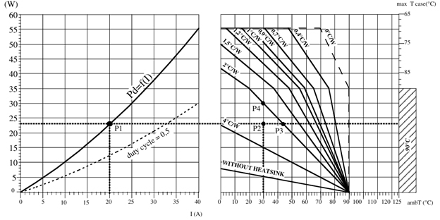
The type of heatsink to be used can be determined directly according to the switched current and the ambient temperature. Previous example with RMS I = 20Amp and max. ambient temperature = 30ºC.
For operating mode, please consult our technical note.
The thermal resistance values in Celduc’s datasheets are based on qualified heatsinks used with their SSRs, ensuring accurate and reliable performance. These values are influenced by factors like airflow and mounting methods. Proper installation, including smooth surfaces and thermal compounds, helps reduce resistance and improve heat dissipation. While general guidelines exist for heatsink sizing based on current ratings, selecting a suitable heatsink can be complex. Users should not rely solely on thermal resistance values but consider testing or consulting the manufacturer to ensure effective cooling in real conditions.
Effective thermal management is not optional when working with solid-state relays—it’s essential. From understanding how heat is generated and transferred, to selecting the right heatsink and ensuring proper installation, every step impacts the performance and durability of the SSR. While general guidelines and datasheets provide useful starting points, real-world conditions often require testing and adjustments. Taking the time to optimize your thermal design will not only protect your components but also ensure safe and reliable operation of your entire system over time.
![]()
D‑U‑N‑S® Number : 117690071
Phone : 312-420-0519
434 E. Main Street, #429
Centerport NY 11721
USA

