


Blog - EXPERTISE & INNOVATIONS - Solid State Relays - Thyristor vs Triac
AC switching solid state relays use back-to-back Thyristors and TRIAC’s as their built-in output switching device. What is the difference between Triacs and Thyristors ?
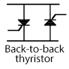
Most common output devices used in AC SSR are silicon-controlled rectifiers (SCRs) and triacs, both are part of semiconductor switches family whose bistable state depends on regenerative feedback. Nevertheless, SCRs-thyristors attractiveness for SSR lies in the ability to switch high power loads, with values up to 125 Amp and high AC lines voltages up to 660 Volts, with less 50 mA of gate drive. In addition, they can withstand one-cycle peak-current surges in excess of around 10 times of their-steady state ratings. Thyristors are control gate diodes. They are conductors in one direction only. Two thyristors should be mounted back-to-back to transmit the 2 half-cycles.
What is the difference between Triacs and Thyristors ?
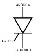
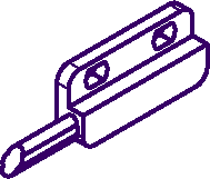
Thyristor also called SCR stands for Silicon Controlled Rectifier.
It is a semiconductor switching device, with two power terminals, called the anode (A) and cathode (K) and one control terminal called the gate (G).
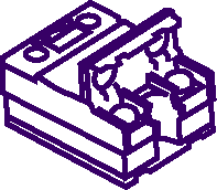
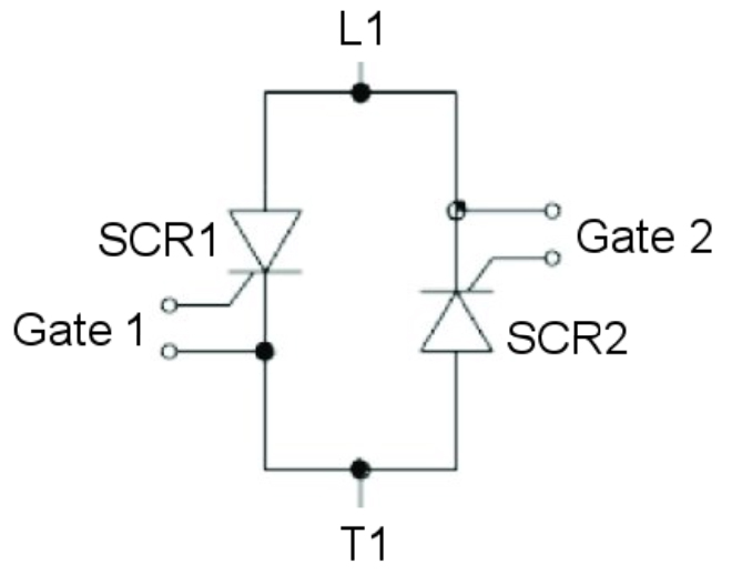
As a diode, the current can only flow through one direction, from Anode to Cathode. To operate on AC mains, the solution is therefore to use 2 SCR connected back to back:
The triggering of the thyristor is done by applying a current pulse positively circulating from Gate to Cathode
The latching of the Thyristor (to switch Thyristor to on-state condition) after a gate current pulse can only occur since :
– Anode-to-Cathode voltage is positive
– Anode-to-Cathode current after trigger exceed the Latching Current.
With the conditions above, the thyristor remains ON even without any current in the gate (Memory effect).
The latch can be reset (Thyristor turns OFF) in 2 cases :
– since Anode-to-cathode current drops below Holding Current
– Since Anode-to-Cathode voltage becomes negative
The regenerative (latching) characteristic of the thyristor provides its high current and surge capability, but it’s also responsible for the thyristor’s sensitiveness to sharply rising voltages, a less desirable characteristic known as dv/dt or rate effect. Unlike a transistor, the SCR cannot be biased to remain in the transitional zone between its blocking and on states. Once regeneration is initiated by an applied gate signal, the transition is rapid, controlled only by internal positive feedback. The magnitude of the gate turn-on signal depends very little on the anode (collector) current, since conduction is controlled internally, however, it is radically affected by gate impedance, anode voltage and junction temperature.
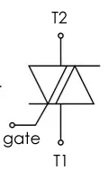
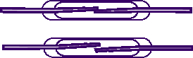
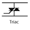
TRIAC stands for TRIode for Alternating Current.
Triacs are semiconductors controlled by the gate capable of conduction in both directions. One single Triac can switch the 2 half-cycles of an alternating network.
Because they are semiconductor devices they cannot ensure a galvanic insulation when they are not controlled. They can even have a dangerous leakage current at OFF state. Furthermore the breakdown often leads to their short-circuit letting the current flow to the load.
This is an important aspect that must be considered to ensure safety in the system design in case of failure or maintenance: The user must ensure the possibility to galvanic isolate the SSR and load part of the circuit with a contactor or a MCB.
These switching elements have a function in common, they only conduct when suitable current is applied to the control electrode (gate). Once in-state conduction, it is maintained, even if there is no gate current, up to zero, or up to at least a current value less than its holding current. In a solid state relay this holding current is usually specified and it is useful when the relay is pulse controlled and it must not be considered as the minimum working current of a solid state relay. Indeed, when the control is applied permanently, if the current is less than the holding current, it is the pilot control circuit of the power component which provides the conduction of the current on the load. SCR and Triac use similar drive circuits, as well, they have equivalent noise and transient susceptible areas.
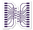
Triacs are based on a single silicon chip whereas back-to-back SCR are 2 separated silicon chips.
This physical difference plays a role in terms of current switching capability:
For load currents up to 25A, triac is a good and easy available solution
From 25A and beyond, back-to-back SCR is the best alternative to ensure high power switching capability.
Should you have any question, please feel free to contact our technical & sales team.
![]()
D‑U‑N‑S® Number : 117690071
Phone : 312-420-0519
434 E. Main Street, #429
Centerport NY 11721
USA

