


Blog - TECHNICAL TIPS & TRICKS - Solid State Relays - Understanding and managing MTBF in Solid State Relays (SSRs)


Solid State Relays (SSRs) are renowned for their high reliability and long operational lifespan compared to electromechanical counterparts. However, like all electronic devices, they are subject to failure. Understanding Mean Time Before Failure (MTBF) is crucial for system engineers to predict reliability, plan maintenance, and ensure overall system availability. This article provides a detailed examination of MTBF in the context of SSRs, analyzing the primary failure mechanisms, key influencing factors like thermal and electrical stress, and practical methods for interpreting and improving reliability data.
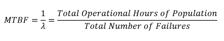
Mean Time Before Failure (MTBF) is a fundamental measure of reliability, representing the projected average time that a device or system will function before a failure occurs.
It is critical to make a distinction for Solid State Relays. SSRs are typically sealed, integrated components. Once they fail, they cannot be repaired and must be replaced. Therefore, the technically correct term is Mean Time To Failure (MTTF). However, in widespread industry practice, MTBF is frequently used interchangeably with MTTF for non-repairable parts. This article will use the common industry term, MTBF, with the understanding that it refers to the time to the first and only failure of the component.
MTBF is not a guarantee of the life of a single unit. A product with an MTBF of 1,000,000 hours will not necessarily last for 114 years. Instead, it is a statistical value derived from testing a large population of units. It indicates that in a large group of these relays operating under defined conditions, one failure can be expected, on average, for every 1,000,000 hours of total accumulated operational time. Mathematically, during the constant failure rate period of a product’s life, MTBF is the inverse of the failure rate (l).
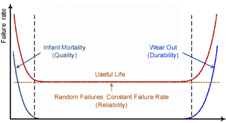
The failure rate of an electronic component over its entire lifecycle is often modeled by the “bathtub curve,” as shown below.
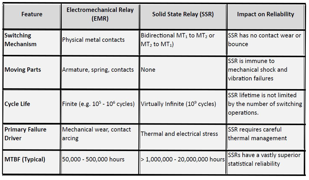
The inherent design of SSRs offers a significant reliability advantage over Electromechanical Relays (EMRs). The absence of moving parts eliminates failure modes associated with contact wear, pitting, and mechanical fatigue.
While the theoretical MTBF of an SSR is very high, its practical reliability is heavily dependent on the operating environment. The single most critical factor is temperature.
The internal power semiconductor (e.g. Triac) dissipates heat whenever it conducts load current due to its on-state voltage drop (typically 1.2V – 1.6V). This heat must be moved away from the internal semiconductor junction to the ambient environment. The relationship between temperature and failure rate follows the Arrhenius equation, which states that the chemical and physical processes leading to failure accelerate exponentially with temperature. A common rule of thumb in electronics is that the failure rate doubles (and MTBF halves) for every 10°C rise in junction temperature (Tj) above its nominal operating point.
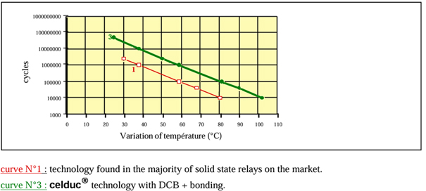
This chart illustrates that as the SSR’s baseplate temperature increases, its predicted MTBF drops precipitously. Operating an SSR without adequate cooling at high loads will drastically reduce its lifespan from millions of hours to potentially just a few thousand or less. To maintain high MTBF, engineers must ensure the junction temperature remains below its maximum rating (typically 125°C or 150°C) by using appropriate heat sinks and ensuring good airflow.
Lightning strikes or inductive load kickback can create voltage spikes exceeding the SSR’s blocking rating, causing immediate dielectric breakdown and permanent failure.
High inrush currents from motors or incandescent lamps can overheat and destroy the output semiconductor before thermal protection can react.
Repeated rapid heating and cooling can cause fatigue in the solder joints and internal wire bonds due to mismatched coefficients of thermal expansion between materials.
High humidity can lead to corrosion, and conductive dust can cause internal short circuits if the SSR’s encapsulation is compromised.
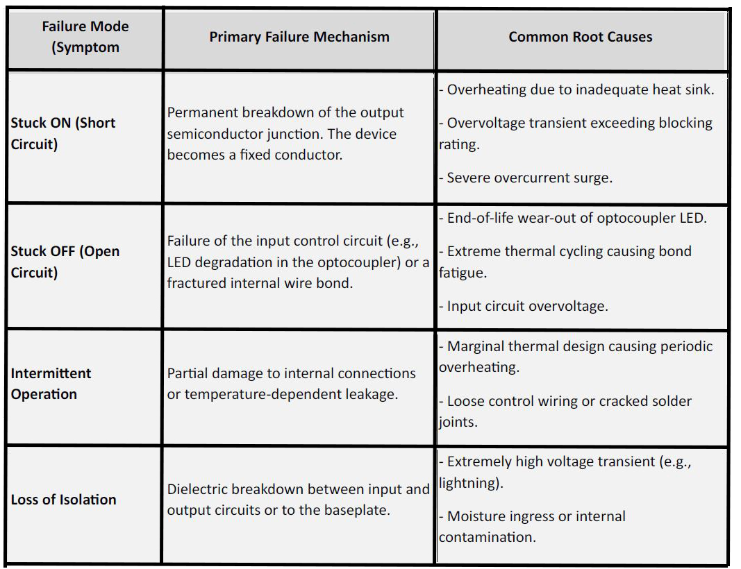
Understanding how an SSR fails is as important as knowing its MTBF. Unlike EMRs, which often fail “open” when contacts burn out, SSRs have a dangerous tendency to fail “shorted.”
Critical Safety Note: Because the most common failure mode is Stuck ON, system designs must always incorporate an independent, mechanical disconnect switch (like a main contactor or circuit breaker) to cut power to the load in case the SSR fails in a conductive state.
HVAC heating application / AC-51 = 37A under 480 VAC three-phase / Ambient temperature: 40°C
SSRs are mounted to an aluminum plate and the heat sink is mounted to the same aluminum plate of the opposite side, thermal paste is applied to both.
Force convection source 500mm below the SSR through a 27 x 222 mm shaft to direct all airflow (approx. 52 CFM or 88m3/hr.) across the full width and fins height of the heat sink.
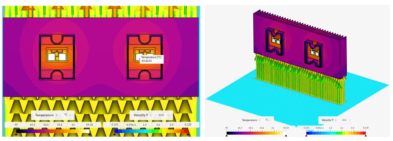
Existing life expectancy data indicates that number of operational cycles of an SSR is directly related to the max temperature reached by the power element, so, the bigger ΔT between thyristors and ambient temperature, the larger degradation of the device. Under forced convection conditions, supplying a powerful airflow induced by the ventilation source (52 CFM), a ΔT = 26ºC is observed, so it is expected that SSR’s number of cycles will be in the order of 65 million, but also considering that highest temperature increase happens in a period of 10 seconds. It means that the maximum cycles of 10 seconds per day possible are 8,640 if the system operates 24/7, the expected years of service are approximately 20.6 years. This prediction assumes there are no external factors to which the SSRs are subjected such as recurrent overcurrent / overvoltage events, excessive inrush current periods or over heating induced from external sources, which will have a negative effect on the life expectancy of the SSR.
The MTBF of a Solid State Relay is a powerful statistical tool that reflects its inherent design reliability. With no moving parts, SSRs offer theoretical MTBF values in the millions of hours, far exceeding electromechanical relays. However, realizing this reliability in practice depends almost entirely on the application design.
Thermal management is paramount. An SSR operated cool will likely outlive the equipment it is installed in. Conversely, an SSR subjected to excessive heat, voltage spikes, or current surges will inevitably fail prematurely, regardless of its datasheet MTBF rating. By understanding the “bathtub curve,” acknowledging the primary failure modes, and strictly adhering to derating curves and protection guidelines, engineers can leverage the full reliability potential of solid-state switching technology.
![]()
D‑U‑N‑S® Number : 117690071
Phone : 312-420-0519
434 E. Main Street, #429
Centerport NY 11721
USA

