


Blog - TRUCS & ASTUCES - Relais statiques - Mini-guide – Correctly sizing a solid state relay (SSR)
In this new article, we provide you with simple and reliable rules to correctly size a solid state relay, by integrating from the design phase the electrical and thermal constraints that determine its service life.
Sizing an SSR begins with a precise analysis of the load to be switched.
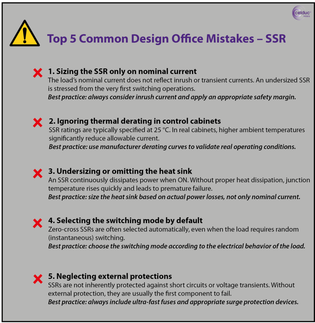
Too often, the choice is limited to the rated current indicated on the machine, whereas this single criterion is insufficient.
A resistive load (heating resistors, ovens, hot plates) presents a relatively stable current and a power factor close to 1. This is the simplest case, but it still requires a safety margin.
Inductive loads (motors, solenoid valves, contactors, transformers) generate high inrush currents at start-up and overvoltages at turn-off. These phenomena place heavy stress on the SSR power component and must imperatively be taken into account from the selection stage.
Capacitive loads, such as switch-mode power supplies or LED drivers, are characterized by very high inrush currents of very short duration. Even if the rated current is low, these peaks can damage an undersized SSR.
In practice, proper sizing therefore requires considering not only the rated current, but also the inrush current, the power factor, and the type of switching required (zero-crossing or instantaneous switching).
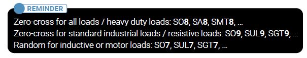
Reminder on our product range coding
The coding of our references makes it easy to quickly identify the load capacity for which each product is designed.
The digits 7, 8 or 9 in the reference directly indicate the corresponding load level, making product selection faster and more efficient.
The rated currents stated in datasheets are generally valid for a reference ambient temperature, most often 40°C, and for ideal cooling conditions.
In a real machine application, the SSR is most often installed in an electrical cabinet, sometimes poorly ventilated, close to other heat-dissipating components. The actual ambient temperature is then significantly higher.
However, the higher the temperature, the lower the permissible current of the SSR. Ignoring this thermal derating effect is one of the main causes of premature failure in the field.
It is therefore essential to consult the derating curves provided by celduc, to correctly size the heat sink and, if necessary, to provide forced ventilation. The objective is to keep the junction temperature of the power component within a safe operating range, even under continuous operation.
 You can download our white-paper to learn the Basics of Heat Sink selection and application
A solid state relay must never be operated continuously at its maximum limit. Unlike an electromechanical contact, it dissipates power permanently in the on-state.
In practice, it is recommended to oversize the rated current of the SSR relative to that of the load. For inductive or capacitive loads, a larger margin is required in order to absorb inrush currents and transients. This approach significantly improves reliability, limits heating, and increases the service life of the component.
Beyond current and temperature, certain parameters are still too often neglected when choosing an SSR. The on-state voltage drop generates thermal losses that must be dissipated. The off-state leakage current can cause problems with certain sensitive loads. Finally, protecting the SSR with ultra-fast fuses or surge-limiting devices is essential in many industrial applications.
It is also necessary to verify compliance with the standards and certifications required by the machine application or the target market.
To conclude, a correctly sized solid state relay is based on three pillars: precise knowledge of the load, control of the thermal environment, and the deliberate integration of a safety margin.
This approach helps to avoid premature failures, improve machine reliability, and secure technical choices from the design phase.
![]()
D‑U‑N‑S® Number : 382274546
Sales department France :
+33 (0) 4 77 53 90 20
Export sales department :
+33 (0) 4 77 53 90 21
———————————-
Gender Equality Index 2026
Based on 2025 data
Final result: 88/100 (for more information)

