


Blog - TECHNICAL TIPS & TRICKS - Solid State Relays - Installation Instructions SSR
In order to get the optimal performances of your solid state relay (SSR) you need to follow our mounting instructions. Here are our top 6 tips for an optimal installation of SSRs.
1-Heatsink mount to allow heat dissipation
2-Using a thermal interface
3-Do not mount SSR on a plastic or painted surface
4-Screw terminals tightening torque between 1,2 and 1,8Nm maximum
5- The heat sink should be positioned with the fins in a vertical position
6- Care must be taken when mounting multiple SSRs in a confined area
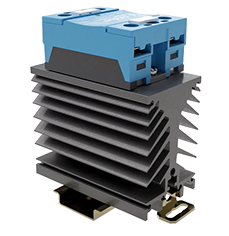
Mounting SSR on heatsink allow to reach nominal current.
The switching component must be suitably cooled so that the junction temperature does not exceed the values specified : usually 125 or 150°C (this value depends on the power components) and so that the temperature of the heatsink does not exceed 90 or 100°C.
The heatsink can be determined either by calculation or directly from the curves provided by celduc.
How to use thermal curves from our technical data-sheets ?
The thermal interface (TIM) helps improving the heat transfer between the relay and the heatsink. As there are cavities between both surfaces and as the air is not good enough to conduct heat, its goal is to fill the voids to increase the heat transfer. Celduc® recommends aluminium material thermal pads with very good thermal performances and no change of state in the long terms.
Thermal Interfaces available at our catalogue : thermal grease (or phase change compound) and thermal pad.
Using Conditions : the surface must be clean, flat and smooth (roughness < 100µm). celduc® guarantees surface flatness for its range of heatsinks.
Thermal grease application : the recommended paste thickness is between 50 and 100µm thick, means that when applying the grease you still have to see the heatsink though it.
For three-phase applications, this is better to use thermal grease as thermal pad is limited in terms of power dissipation.
Our Solid State Relays should also never be mounted to a plastic base or to painted surfaces. Except if using conditions allow this (switching current, ambient temperature).
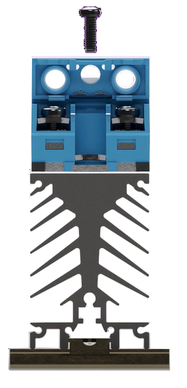
With two screws, first tighten both screws with max. 1 Nm and then continue with nominal torque 1.8Nm. It is recommended to use an electric powered screw-driver rather than a pneumatic tool. The specified tightening parameters can be better adjusted and especially the final torque will be reached more smoothly. With pneumatic systems, shocks and torque overshoot can occur. A limitation of the mounting screw velocity is recommended to allow the thermal paste to flow and spread equally, especially if a more dense paste is used. If tightened with high velocity internal damages can occur. The maximum screw velocity for tightening should not exceed 250 rpm. A soft tightening (no torque overshoot) will reduce internal stress.
The heat sink should be positioned with the fins in a vertical position with an unimpeded air flow. The vertical mounting will aid in heat dissipation.
![]()
A sufficient clearance of minimum 1x heatsink width should be available all around the SSR to allow air circulation, and then get 100% of the SSR performances.
If no space between two SSRs, nominal current must be derated by 30%.
Before using our SSR, please read all mounting instructions and technical data-sheets available on : www.e-catalogue.celduc-relais.com and test in real conditions with SSR baseplate temperature < 100°C.
Watch now our quick tutorial video to learn how to install a Solid State Relay (SSR) to get optimal performances :
![]()
D‑U‑N‑S® Number : 382274546
Sales department France :
+33 (0) 4 77 53 90 20
Export sales department :
+33 (0) 4 77 53 90 21
———————————-
Gender Equality Index 2026
Based on 2025 data
Final result: 88/100 (for more information)

